Rigid-flex printed circuit boards (R-FPCBs), also known as rigid-flex boards or rigid-flexible boards, are commonly referred to as rigid-flex boards.
An R-FPCB is a printed circuit board (PCB) that combines rigid and flexible regions interconnected by conductive patterns.
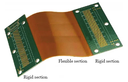
It combines the characteristics of both flexible printed circuit boards (FPCBs) and rigid printed circuit boards (RPCBs), as shown in Figure 1.
Engineers value R-FPCBs for their combined rigidity and flexibility advantages, leading PCB designers to favor them and adopt them in an increasingly wide range of applications.
Designers develop different R-FPCBs with distinct structural and performance characteristics, making each type suitable for specific applications.
This article provides a detailed introduction to the types of R-FPCBs and their respective features.
Flexibility of R-FPCBs
R-FPCBs consist of two parts: a rigid section and a flexible section.
Based on the flex characteristics of the flexible section, R-FPCBs can be further classified into the following three categories:
① Dynamic-bending R-FPCBs: During use, these products can withstand repeated bending.
Engineers typically avoid placing through-holes in the flexible section and do not mount components there.
Designers use this section primarily to provide electrical connections for the rigid section.
② Static-bending R-FPCBs: These products undergo minimal bending deformation after installation;
③ Engineers define bending-type R-FPCBs as products that undergo arched bending only during installation and maintenance.
Designers specify a large bending radius for these products, and they do not allow folding or continuous flexing.
For semi-flexible R-FPCBs, engineers select a glass-fiber-reinforced rigid substrate instead of a flexible film.
Designers achieve the required flexibility by reducing the thickness only in the bending areas.
The flexural performance of R-FPCBs primarily depends on the materials and structure of the flexible regions, which are essentially the same as those of FPCBs.
Layer Structure of R-FPCBs
There is no single-sided R-FPCB; if it features only a single-sided circuit design, the rigid substrate contains no circuit patterns and serves solely as a reinforcement board.
Engineers do not classify flexible boards designed in this manner as true R-FPCBs, since combining an FPCB with a reinforcement board does not produce an equivalent R-FPCB.
Within the flexible region of an R-FPCB, designers implement conductor traces as single-layer, double-layer, or multi-layer configurations.
As the number of layers increases, the product becomes more complex.
Engineers bond the upper and lower layers in double-layer or multi-layer flexible conductor circuits using an adhesive film to form an integrated structure.
Designers also create R-FPCBs with an air gap between the upper and lower layers to achieve superior flexibility.
To accurately represent the layer structure of an R-FPCB, engineers indicate the total number of layers in both the rigid and flexible sections (R+F).
For example, when the rigid section of a PCB contains 6 layers and the flexible section contains 2 layers, engineers designate it as an R-FPCB (R6+F2).
Engineers do not limit HDI to rigid PCBs; they apply its lamination process to multilayer FPCBs and R-FPCBs, enabling miniaturization and thin-profile designs for both FPCBs and R-FPCBs.
Since some smart devices require HDI applications, in addition to requirements such as stacked structures, copper-filled vias, and fine lines, they must also be bendable and flexible.
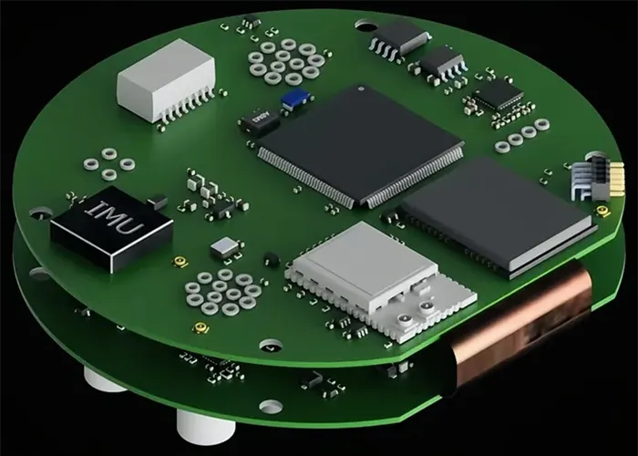
Therefore, combining HDI with R-FPCB offers additional advantages, as illustrated in Figure 2.
Structural Configuration of R-FPCBs
R-FPCBs have the same shape as flexible printed circuit boards and can take on a wide variety of forms. Their basic structural types include the following.
Symmetrical R-FPCB
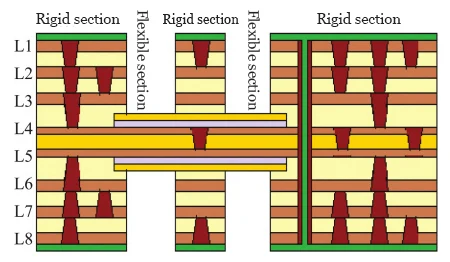
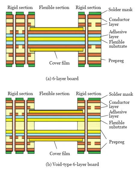
Engineers define a symmetrical R-FPCB as a standard type in which the flexible circuit layer sits between rigid layers.
Designers arrange the rigid and flexible sections symmetrically above and below each other, as shown in Figure 3. This structure provides robustness and reliability.
The rigid and flexible regions of an R-FPCB interconnect electrically. As a result, engineers allow the flexible circuit to extend locally into the rigid region and function as an inner layer.
When a cover film exists on the flexible circuit extending into the rigid area, engineers must evaluate how differences in processing properties between the rigid substrate and the flexible substrate affect the bonding strength of the inner layer within the rigid area.
For this reason, designers avoid applying a cover film to the flexible circuit extending into the rigid area whenever possible.
Asymmetric R-FPCB
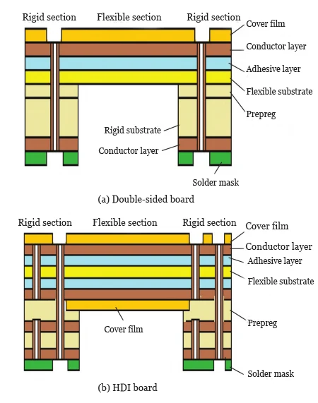
An asymmetric R-FPCB refers to a design in which the flexible circuit layer is not located in the middle layer of the rigid section;
Instead, the rigid and flexible sections are arranged asymmetrically, as shown in Figure 4.
Flying-Tail Type R-FPCB
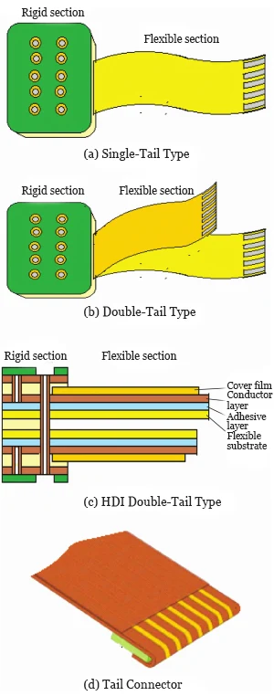
Engineers configure the flying-tail type R-FPCB so that one end of the flexible board connects to a rigid board, while the opposite end, resembling a tail, moves freely, as shown in Figure 5.
Designers may incorporate multiple flexible tails. During installation, technicians connect the flexible sections of the flying-tail type to fixed connectors, demonstrating the flexibility of the connection.
Book-Type R-FPCB
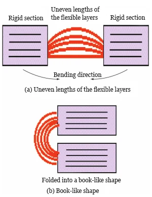
Engineers design a book-type R-FPCB by connecting two thick rigid multilayer boards with a flexible multilayer board. The flexible section functions like the spine of a thick book and allows bending.
To ensure smooth bending performance, designers introduce air gaps between the rigid layers in the flexible multilayer, and vary the lengths of the individual layers, as shown in Figure 6.
The bending radius of the flexible section gradually increases from the inner side to the outer side, and the length of the flexible layers increases accordingly.
This increase generally follows the principle of 1.5 times the thickness of a single layer.
The actual increase varies depending on the tightness of the bend and the number of layers. Engineers recommend performing modeling verification before proceeding to formal manufacturing.
Special-Purpose R-FPCBs
Shielded R-FPCBs
As the application areas of R-FPCBs continue to expand, various specialized types of R-FPCBs have emerged in this field.
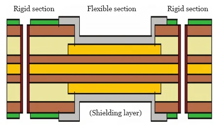
To reduce electromagnetic interference (EMI) affecting the signal layers, engineers design a mesh power or ground plane in the rigid section of the R-FPCB to shield against EMI.
Technicians then coat the flexible section with conductive paste or conductive film to form a shielding layer, producing a shielded R-FPCB, as shown in Figure 7.
Thermally Conductive R-FPCBs
Engineers address thermal management and heat dissipation requirements for R-FPCBs by incorporating methods such as metal backplanes, metal core boards, or embedded copper blocks into the rigid sections to handle high-power, high-heat circuits. Designers may also use thick copper conductors for additional thermal performance.
These methods improve heat dissipation in the rigid areas of R-FPCBs, enabling engineers to design highly thermally conductive R-FPCB products.
Buried Component RF-FPCB
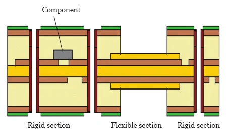
To increase the component density of PCBs, engineers develop innovative designs for component mounting.
In this approach, manufacturers no longer mount components on the surface as in traditional methods but instead embed them within the inner layers, resulting in a buried component PCB.
Similarly, engineers embed components within the rigid regions of a rigid-flex PCB to form a buried component RF-FPCB, as shown in Figure 8.
Expandable R-FPCBs
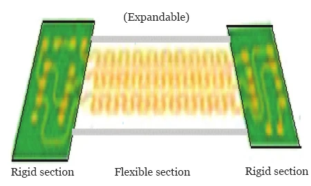
Engineers combine rigid boards with expandable flexible boards to form expandable R-FPCBs, as shown in Figure 9.
Manufacturers widely adopt this type of R-FPCB in wearable electronics and medical devices.
Standard Manufacturing Process for Rigid-Flex Boards
The manufacture of rigid-flex printed circuit boards combines two technologies: rigid printed circuit boards and flexible printed circuit boards.
The manufacturing process follows a standard sequence. Engineers first process the flexible section using a flexible substrate and process the internal conductor patterns for the rigid section using a rigid substrate.
Technicians then laminate the two sections together and establish electrical interconnections through drilling and via plating.
After pattern formation, surface finishing, and contour machining, manufacturers produce the final, complete circuit board.
A key step in this process requires engineers to window or cover the adhesive film on the flexible section with a release film before lamination, preventing the rigid layer and the flexible section from adhering to each other.
Finally, technicians remove (de-laminate) the rigid cover layer over the flexible section, enabling the flexible section to bend.
Manufacturers then trim the board using mechanical milling or laser cutting methods to complete the finished rigid-flex printed circuit board.
Conclusion
To meet growing and increasingly diverse demands, R-FPCBs have evolved into a wide range of types, providing multifunctional, compact, and highly reliable electronic interconnection platforms for various electronic devices.
Designers give full rein to their imagination to create innovative R-FPCB designs, while manufacturers leverage their expertise to bring these concepts to life.
However, as product complexity increases, so do costs, and further research into this issue will be necessary in the future.