As you open and close a foldable smartphone, or slip a smart ring onto your finger, did you know that behind these bendable and foldable electronic devices lies a flexible circuit board—seemingly simple yet packed with technology—silently holding everything together?
Flexible Printed Circuits (FPCs) serve as critical components—as thin as a cicada’s wing, yet found everywhere.
Today, from a hardware engineer’s perspective, I’m bringing them out from behind the scenes to introduce you to this indispensable “Transformer” of modern smart devices.
I liken it to Mystique from the X-Men. It bends, rolls, and folds freely, moving and expanding in three-dimensional space.
Under the same current-carrying capacity, FPCs are approximately 90% lighter than rigid PCBs and save 60–90% in space.
With a thickness of less than 0.1 mm, they have become the “lifeline” of smartphones and wearable devices.
The Three Key Advantages of FPC
Space Magician—Thickness as Thin as 0.1mm
For example, as shown in the figure, the FPC cables in various smartphones are bent to follow the contours of the device’s internal structure.
This allows for flexible routing based on the positions of components, enabling the cables to bypass large components such as batteries and chips to connect parts in different areas.
By fully utilizing narrow gaps, it ensures signal connectivity between all components. Without it, smartphones would be 2mm thicker.

Transformers: Bending, Rolling, and Folding
In space-constrained applications—whether in aerospace, wearable devices, or other space-sensitive fields—FPC’s ability to bend, roll, and fold sets it apart.
When you encounter products like these, you can’t go wrong by choosing FPC.

The Master of Reliability—Used in Automotive and Industrial Security Equipment
The flexible structure of FPCs effectively absorbs vibrations and shocks.
In complex environments such as automotive and industrial security equipment, FPCs have a failure rate that is more than 60% lower than that of traditional wiring harnesses.

The Many Facets of FPC
Classification by Conductive Copper Layer:
Single-layer boards: The simplest structure, resembling a “one-way street” for circuits.
Through-hole boards without a shielding layer serve a similar function to FFCs, providing only a simple connection.

Double-sided board: Features pads on both sides and is primarily used to connect to other circuit boards; it is equivalent to a single-sided board.

Double-sided/multi-layer boards: These come into play when circuits become complex, acting as a sort of “interchange system” for the circuitry.

Roles Based on Functionality:
These materials are widely used in numerous fields, including cable assemblies, printed circuits, connectors, and multifunctional integrated systems.
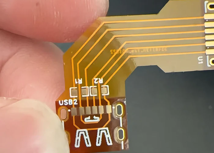
FPC + PI reinforcement = gold-finger connectors (see image below).
FPC + RF4 reinforcement = FPC + ultra-thin boards suitable for SMT assembly.

(Without reinforcement, surface-mount components can be placed using a jig; however, since the PCBA is not structurally supported, it is prone to damage and is not recommended.)

FPC + multilayer lamination = rigid-flex boards; high-end products, drones, VR headsets, precision headphones…

The Versatility of FPCs—Adaptable to Multiple Applications
Consumer Electronics: Your Personal Assistant
Smartphones are the largest users of FPCs, with an average of 12 to 20 FPCs used in a single device.
The flexible circuits in the camera hinge must withstand millions of bends without compromising functionality.

Automotive Electronics: A Driving Force Behind Weight Reduction
In new energy vehicles, replacing some wiring harnesses with FPCs can reduce weight by 40% and cut installation space by 60%—a critical factor in extending driving range.
With demand for FPCs per vehicle expected to exceed 100 units, this alone is enough to keep layout engineers busy for a month.

Medical Electronics: Guardians of Health
In wearable medical devices, the “flexibility” of FPC truly shines.
Take wearable blood glucose monitors, for example: by integrating sensors and data transmission modules via ultra-thin FPC, these devices can bend freely with the body’s movements even when attached to the skin.

Getting Down to Business: FPC Hardware Design Levels
Getting Started: Able to design single-sided or double-sided straight-through FPCs.
Gaining Proficiency: Able to design double-sided cross-connected and shielded FPCs.
Mastering the Craft: Able to design FPCs for rigid-flex boards.
Reaching Mastery: Able to design FPCs that are easy to assemble, provide effective shielding, and withstand high voltage.
Practical Tips: Hardware Design Details for FPCs
Detail 1: How to Tell at a Glance if an FPC Is Properly Seated?
During production, we’ve encountered cases where certain boards malfunctioned because the FPC wasn’t properly seated.
Why wasn’t it properly seated? Because assembly line workers couldn’t reliably confirm that each one was seated correctly.
How can this problem be solved? Design a white line to indicate proper seating (the FPC is seated when it aligns with the lower edge of the ZIF socket).

Detail 2: How can non-1-to-1 FPCs ensure that employees do not insert the connector upside down?
In addition to marking white lines as described above, a solution to this problem involves adding silk-screen printing on both sides of the board.
The text must be large enough.

In cases like this, where the number of pins on both sides is the same but the circuits aren’t connected in a one-to-one straight-through configuration—with power and ground lines—inserting the connector the wrong way will burn out the board.
Minor issues include overheating and malfunction; severe cases can result in smoke and sparks.
Detail 3: When dealing with wide FPCs during assembly, how can we ensure a high production yield if the routing is damaged?
Break it down into smaller sections. This approach is suitable for multi-pin, wide FPCs where the VOUT area is empty in the middle.
By merging these sections during assembly, the width is reduced, and flexibility is increased.

Come on, take a look at how it looks when assembled. It fully leverages the FPC’s ability to bend, coil, and fold freely—nothing can stop it.

Detail 4: How to dissipate heat when an FPC generates excessive heat due to prolonged high current?
To reduce temperature (i.e., ensure adequate heat dissipation), use a multi-pin power supply and a multi-pin ground (GND) network with windowing for spacing as small as 0.5 mm. Use 2-ounce thick copper.
For wider traces, a spacing of 1.0 mm is permitted, with wiring on both sides.

Detail 5: How should ESD be handled for FPC connectors?
Open a window in the ground plane shielding on the back side, as shown in the figure below, and connect it to the enclosure—a common practice in smartwatches.

Detail 6: How can stress-induced damage be mitigated in narrow FPCs during production?
Take Apple products as an example: to enhance their flexibility and fatigue resistance, they incorporate a spring in the center and use a curved design near the operational area to absorb stress, thereby preventing the FPC from breaking due to rigid pulling during assembly.

Follow-up: Does FPC serve any other purpose besides connectivity?
Yes, it acts as an antenna! For example, 2.4 GHz or Bluetooth devices use FPC antennas that utilize a quarter-wavelength (λ/4) design.

There are also FPC coils, which use copper foil on a flexible printed circuit (FPC) etched into a “coil shape” to replace traditional enameled wire in coil winding; their primary function is to serve as “induction coils” for energy transfer.

As technology advances, we may see more innovative applications, such as implantable electronic devices and electronic skin; the future of FPC holds endless possibilities.
Conclusion
Flexible printed circuits (FPCs) have become a foundational technology in modern electronic design, enabling the next generation of compact, lightweight, and highly integrated devices.
From smartphones and wearable electronics to automotive systems and medical equipment, FPCs provide the mechanical flexibility and electrical reliability required for increasingly complex product architectures.
Beyond simple connectivity, flexible printed circuits (FPCs) now play multifunctional roles—including signal transmission, thermal management, structural adaptation, antenna integration, and even energy transfer.
Their ability to bend, fold, and conform to three-dimensional spaces makes them indispensable in overcoming spatial constraints that rigid PCBs cannot address.
However, successful FPC implementation depends heavily on thoughtful design.
Considerations such as reinforcement structures, assembly alignment, heat dissipation, ESD protection, and mechanical stress control directly determine product reliability and manufacturing yield.
As shown in practical engineering examples, small design details often have a significant impact on overall performance and durability.
Looking ahead, flexible printed circuits (FPCs) will continue to evolve alongside emerging technologies such as foldable devices, wearable health systems, autonomous vehicles, and electronic skin.
With ongoing advances in materials, manufacturing precision, and system integration, FPCs are set to play an even greater role in shaping the future of intelligent electronics.