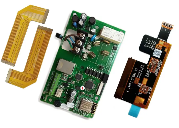
In modern electronic devices, printed circuit boards (PCBs) serve as the carrier for electronic components and the bridge for electrical connections; the choice of PCB type directly impacts product performance, reliability, and cost.
As electronic products evolve toward lighter, thinner, smarter, and more highly integrated designs, the three primary types of circuit boards—PCB (printed circuit board), FPC (flexible printed circuit), and FPCB (flexible printed circuit board)—each demonstrate unique advantages and application value.
This article will provide an in-depth analysis of the technical characteristics, application scenarios, and selection strategies for these three types of circuit boards.

PCB: The Cornerstone of Rigid Circuit Boards
PCB (Printed Circuit Board) typically refers to rigid circuit boards, which are the most fundamental and widely used type of circuit board in the electronics industry.
Technical Features:
1. Base Material:
Primarily FR-4 fiberglass epoxy resin; metal substrates (aluminum or copper) or ceramic substrates are used for certain specialized applications.
2. Structure Types:
Classified by the number of layers into single-sided, double-sided, and multilayer boards (commonly 4–8 layers, with a maximum of 64 layers).
3. Physical Properties:
Rigid structure, high mechanical strength, resistant to bending and deformation; thickness typically ranges from 0.2 mm to 2.0 mm
4. Manufacturing Processes:
Utilizes mature processes such as drilling, electroplating, and standard etching; highly standardized
Advantages:
1. High Reliability:
The rigid structure provides stable mechanical support, making it suitable for supporting heavy-duty components
2. Cost Advantage:
Mature production processes result in lower costs for mass production
3. Design Flexibility:
Supports advanced technologies such as high-density interconnect (HDI) and buried/blind vias
4. Excellent Thermal Performance:
Metal substrates, in particular, offer superior thermal conductivity
Application Scenarios:
1. Fixed-Installation Equipment:
Computer motherboards, home appliance control boards, communication base stations
2. High-Frequency, High-Speed Applications:
5G base stations, AI servers, new energy vehicle electronic control systems
3. Heat-Sensitive Applications:
LED lighting, electric vehicle IGBT modules
FPC: A Revolution in Flexible Circuit Boards
FPC (Flexible Printed Circuit), also known as a flexible circuit board or “soft board,” is made from a flexible substrate and features bendable and foldable properties.
Technical Features:
1. Substrate Material:
Polyimide (PI) or polyester film (PET) is primarily used as the flexible substrate.
2. Structural Design:
Extremely thin (0.05–0.20 mm), lightweight, and capable of dynamic bending
3. Manufacturing Processes:
Utilizes specialized techniques such as laser cutting, lamination with cover films, and precision etching
4. Technical Specifications:
Minimum line width/spacing of 50/50 μm; supports over 1,000 cycles of dynamic bending
Advantages:
1. Spatial Adaptability:
Can be bent and folded to adapt to three-dimensional layouts, saving internal device space
2. Thin and Lightweight:
Thickness is only 1/3–1/4 that of rigid PCBs, suitable for ultra-thin device designs
3. Vibration Resistance:
The flexible structure better absorbs vibrations and impacts
4. Design Flexibility:
Enables complex 3D routing, replacing traditional cable connections
Limitations:
1. Higher Cost:
Flexible materials and specialized manufacturing processes result in higher costs compared to rigid PCBs
2. Limited Load-Bearing Capacity:
Not suitable for soldering large or heavy components
3. Poor Heat Dissipation:
Limited heat dissipation capability compared to metal-based PCBs
4. Restrictions on Multi-layer Design:
Multi-layer FPCs reduce flexibility and increase costs
Application Scenarios:
1. Dynamic/Compact Spaces:
Foldable smartphone flex cables, drone gimbals, wearable devices
2. Lightweight and Slim Requirements:
Camera modules, battery connection cables, medical endoscopes
3. Cutting-edge Innovation Fields:
AR/VR devices, flexible sensors for humanoid robots
FPCB: Terminology Clarification and Conceptual Analysis
Regarding the term FPCB (Flexible Printed Circuit Board), its meaning requires specific clarification:
Terminology Definition:
1. Relationship Between FPCB and FPC:
In most industry contexts, FPCB and FPC are synonymous terms, both referring to flexible printed circuit boards
2. Potential Confusion:
In rare cases, FPCB may be interpreted as “Flexible Printed Circuit Board Assembly,” but this is not standard industry usage
3. Standard Terminology:
The industry typically uses “FPC” to refer to flexible circuit boards, while “PCB” specifically refers to rigid circuit boards
Technical Essence:
An FPCB is essentially an FPC, utilizing the same flexible substrate (polyimide (PI) or polyester (PET)) and possessing the same bendable characteristics.
Its manufacturing processes, technical parameters, and application scenarios are identical to those of an FPC.
Industry Recommendation:
To avoid confusion, it is recommended to uniformly use the term “FPC” in technical documentation and procurement specifications, while reserving ‘PCB’ exclusively for rigid circuit boards.
For composite structures containing flexible sections, the specific term “Rigid-Flex PCB” should be used.
A Detailed Comparative Analysis of the Three Major Types
| Aspect | PCB (Rigid PCB) | FPC/FPCB (Flexible PCB) | Rigid-Flex (Rigid-Flexible PCB) |
|---|---|---|---|
| Base Material | FR-4 glass fiber, copper foil, epoxy resin | Polyimide (PI), polyester (PET) | FR4 rigid material + flexible FR4 material |
| Flexibility | Not flexible, mechanically strong | Flexible, bendable, adaptable to dynamic environments | Partially flexible, partially rigid |
| Typical Thickness | 0.2mm–2.0mm | 0.05mm–0.20mm (standard) | 0.6mm (entire board) |
| Layer Count | 1-64 layers of copper | 1-8 layers of special materials | As per design requirement, clean composite |
| Smallest Line/Spacing | 4mil/4mil (approx. 100µm) | 2mil/2mil (approx. 50µm) | Between the two layers |
| Processing Technology | Drilling, electroplating, standard processes | Laser cutting, film lamination, precision etching | Combination of both techniques, with complexity |
| Cost Comparison | Low (standard process) | High (material cost, processing) | Highest (engineering complexity) |
| Heat Performance | Excellent (especially for copper boards) | General | Best for materials with high thermal tolerance |
| Durability | Excellent (FR4’s Tg value > 130°C) | Moderate (PI with high tolerance 260°C) | Best for industrial materials |
| Dynamic Aging Life | Not applicable | >1000 cycles (optimized design) | Limited cycles (optimized design) |
| Main Uses | Fixed installations, high-frequency, large equipment | Flexible circuits, space-saving, light equipment | Combination of both rigid and flexible needs |
Differences in Manufacturing Processes and Technologies
Characteristics of PCB Manufacturing Processes:
1. Substrate Processing:
Rigid substrates are used, and a stable structure is formed through a lamination process.
2. Drilling Technology:
Primarily mechanical drilling is used, with minimum hole diameters of 0.15 mm (laser) or 0.25 mm (mechanical).
3. Surface Treatment:
Common processes include tin plating, electroless gold plating, and OSP (anti-oxidation).
4. Solder Mask:
Printed using liquid solder mask ink
FPC Manufacturing Process Characteristics:
1. Flexible Substrate Processing:
Uses PI or PET film, requiring a specialized thermal lamination process
2. Precision Processing:
Laser drilling can achieve a minimum hole diameter of 0.10 mm
3. Cover Layer Process:
Uses a protective film (e.g., PI cover film) to replace the solder mask found on rigid PCBs
4. Reinforcement Design:
Adding PI/FR-4/metal reinforcement plates in connector areas to provide mechanical support
Manufacturing challenges for rigid-flex boards:
1. Process Integration:
Requires production equipment capable of handling both FPC and PCB manufacturing
2. Laminating Technology:
Bonding the flexible and rigid sections requires specialized lamination processes
3. Yield Control:
The production process involves numerous steps, resulting in lower yield rates and higher costs
Selection Guide
Space Constraints:
Ample space, requiring component support → Choose PCB
Compact space, requiring bending or folding → Choose FPC
Complex structure, requiring both rigid and flexible sections → Choose rigid-flex PCB
Performance Requirements Analysis:
High-frequency signal transmission (e.g., 5G) → Choose high-frequency PCB (e.g., PTFE material)
Extreme temperature environments (aerospace) → Choose ceramic substrate PCB
Thin-profile and dynamic transmission requirements → Choose PI substrate FPC
High-power heat dissipation requirements → Choose metal-core PCB
Balancing Cost and Mass Production:
Mid-to-low-end high-volume production → PCB offers a significant cost advantage
Small-batch, high-end innovative products → FPC offers better flexibility and adaptability
Specialized, complex structures → Rigid-flex boards, though more expensive, can address specific requirements
Reliability Assessment:
High-vibration environments → FPC’s flexible structure better absorbs vibrations
Long-term static installation → PCB’s rigid structure is more stable and reliable
Dynamic bending applications → Requires specially designed dynamic-bending FPC
Technology Trends and Market Outlook
Trends in Technology Convergence:
As electronic product designs become increasingly complex, a single type of circuit board often struggles to meet all requirements.
Rigid-flex PCBs, as a fusion of rigid PCBs and flexible printed circuits (FPCs), are gaining widespread adoption in high-end applications.
This hybrid design provides stable support in rigid areas while enabling flexible connections in flexible areas, making it particularly suitable for complex applications such as the hinge zones of foldable smartphones and automotive electronics.
Material Innovation Directions:
1. High-Frequency Materials:
5G/6G communications are driving the development of high-frequency, high-speed PCB materials, such as modified polytetrafluoroethylene (PTFE).
2. Flexible Substrates:
New flexible materials, such as liquid crystal polymers (LCP), demonstrate excellent performance in RF applications.
3. Thermal Management Materials:
Demand is growing for high-thermal-conductivity metal substrates and ceramic substrates in the power electronics sector.
Expansion of Application Areas:
1. Automotive Electronics:
As vehicles become smarter, the number of onboard sensors is increasing, driving continued growth in FPC penetration
2. Medical Devices:
Wearable medical devices and implantable devices are driving strong demand for flexible printed circuits
3. Artificial Intelligence:
AI servers require high-performance PCBs to support high-speed signal transmission
4. Internet of Things (IoT):
Miniaturized, low-power devices are driving the development of ultra-thin FPCs
Manufacturing Technology Upgrades:
1. Precision Processing:
Line widths and spacing are becoming smaller; FPCs have achieved 50/50 μm processes
2. Multilayer Flexible Boards:
Manufacturing technology for FPCs with 8 or more layers is gradually maturing
3. 3D-Printed Circuits:
Additive manufacturing technology offers new possibilities for circuit boards with special shapes
Summary and Recommendations
PCBs, FPCs, and rigid-flex boards each have their own unique technical advantages and application scenarios.
When making a selection, it is necessary to comprehensively consider product requirements, cost budgets, and technical feasibility.
Core Selection Principles:
1. Prioritize Functional Rrequirements:
Select the most suitable circuit board type based on the device’s space constraints, motion characteristics, and signal requirements.
2. Balance Performance and Cost:
Choose the most cost-effective solution while ensuring performance requirements are met.
3. Focus on Reliability Requirements:
For critical applications, prioritize long-term reliability and environmental adaptability.
4. Consider Manufacturing Feasibility:
Evaluate suppliers’ technical capabilities and production yield rates.
Future Development Trends:
As electronic products continue to evolve toward lighter, thinner, highly integrated, and multifunctional designs, the scope of flexible circuit board applications will expand further.
At the same time, rigid-flex technology will mature, providing superior solutions for complex electronic devices.
Advances in materials science will also drive continuous improvements in PCB performance, meeting the higher demands placed on PCBs by emerging fields such as 5G, artificial intelligence, and the Internet of Things (IoT).