
In the field of PCB design, rigid-flex PCBs offer unique solutions for modern electronic devices thanks to their diverse shapes and sizes.
Some rigid-flex PCBs—such as those used in hearing aids—pose significant manufacturing challenges due to their small size.
However, regardless of size, the design of the transition zone between the flexible and rigid sections affects reliability during both manufacturing and use.
Manufacturing and assembly processes, as well as various real-world usage scenarios, subject the transition zone to mechanical and thermal stresses.
Therefore, designers must be fully aware of the potential risks associated with poor design.
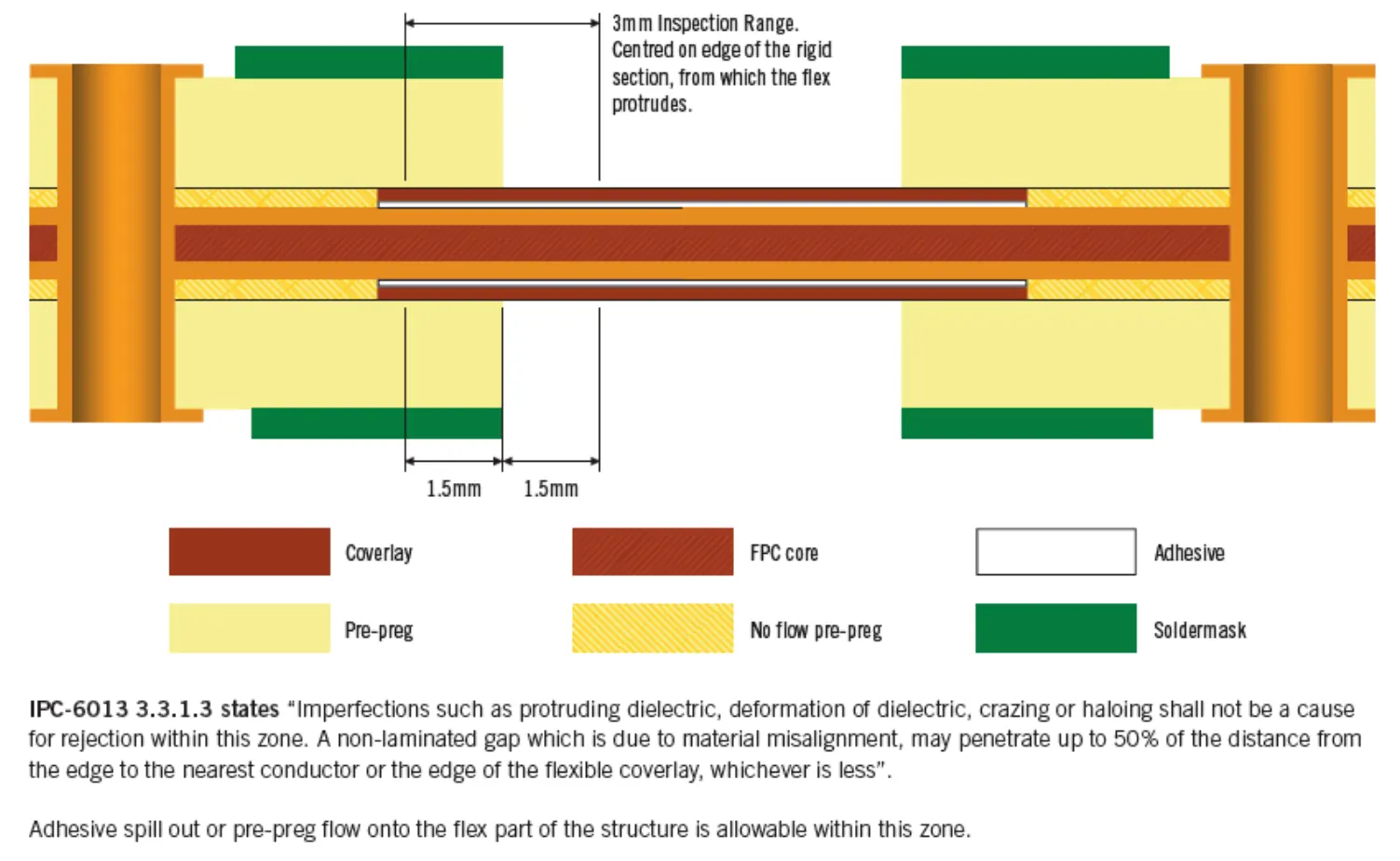
The IPC-6013 standard defines the transition zone of a rigid-flex PCB as a 3-mm-wide area centered on the axis of the rigid board’s edge (see figure below).
This article will delve into the design considerations and manufacturing precautions for this critical area to help you avoid potential risks.
Unique Challenges in the Manufacturing Process
The production process for rigid-flex boards differs from that of conventional rigid boards.
After lamination of the flexible section is complete, all materials undergo a final press to bond the flexible and rigid sections together.
Prior to the second press, manufacturers insert spacers into the stack to prevent resin from flowing into the flexible section;
A milling process subsequently removes these spacers from the flexible section.
The figure above also lists some acceptable defects within the transition zones.
If any functional features are routed within these transition zones, these defects may adversely affect the final performance of the rigid-flex PCB.
The following are some common defects and their effects:
Crazing and Haloing: At the junction between the rigid and flexible boards, material delamination, resin cracks, or copper foil fractures may occur.
This is primarily due to the rigid board being thick and the flexible board being thin.
As a result, a stepped structure forms after lamination.
During bending or thermal cycling, stress concentrates entirely near the transition line.
Lamination Voids: Lamination voids within the transition zone are acceptable.
Rigid-flex PCBs typically use FR4 material and polyimide.
In standard rigid PCBs, the prepreg flows and bonds the copper layers, preventing interlayer voids.
However, the FR4 prepreg used in rigid-flex PCBs has “low-flow” or “non-flow” characteristics, which prevent resin from flowing into the flexible board area;
Consequently, lamination voids may occur in the transition zone.
Resin squeeze-out occurs even though PCB manufacturers use non-flowing PP to produce rigid-flex PCBs.
In some cases, resin from the bonding material can still squeeze out from the edges of the rigid section into the transition zone.
This may not be an issue for “Flex to Install” applications; however, for “Dynamic-Flex” applications, the sharp edges of the cured resin may damage the flexible section.
Protruding Rigid Dielectric: When milling the flexible board area, lamination voids or resin squeezeout may cause the rigid board dielectric layer to protrude slightly.
This defect does not affect performance and is acceptable according to the IPC-6013 standard.
Copper Deformation: Due to material instability in the transition zone, copper features are prone to deformation and may even crack or delaminate.
This occurs because the copper may obstruct resin flow, resulting in insufficient resin coverage.
Additionally, poor interlayer alignment accuracy may occur.
Coverlay Protrusion: Placing coverlay material in the transition zone can also cause problems.
Coverlay is not designed to bond with FR4 material;
If it extends into the transition zone, poor adhesion may lead to delamination.
Feature Design in Transition Zones: Risks and Considerations
A key question is: How far can functional features extend into the transition zone without compromising product performance or causing excessive stress on the material?
The answer is: it is virtually impossible to extend them.
As shown in Figure 2, it is technically feasible to design and manufacture features within the transition zone.
It is also possible to place features in the flexible board area. However, this is not standard practice.
Therefore, close communication with your PCB supplier is essential.
The PCB supplier’s technical team understands the limits of each process capability.
They will advise you on the available space within the transition zone based on the factory’s capabilities and specifications.
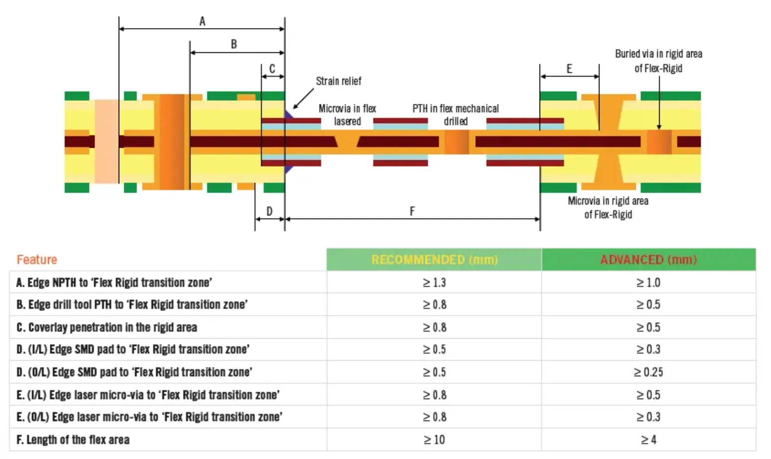
In Figure 2, the recommended values listed on the left carry the lowest risk.
If you use the specifications in the “Advanced” column on the right, you should exercise extra caution and ensure that all stakeholders are fully aware of the potential risks.
Trend Toward Miniaturisation and Advances in Manufacturing Capabilities
As circuit technology continues to evolve, new solutions and manufacturing processes are constantly emerging to meet the growing demands of today’s products.
The trend toward miniaturisation is pushing the limits of rigid-flex PCB manufacturing processes.
NCAB consistently encourages the pursuit of innovation and cutting-edge technology in PCB design, provided that such innovations meet application requirements.
It also ensures that all stakeholders are fully aware of the potential risks.
While some PCB manufacturers are capable of producing rigid-flex boards with small transition zones, we remain cautious.
We recommend subjecting them to rigorous quality testing.
Additionally, when designing, please note the following:
Avoid placing critical functional features in transition zones;
Communicate with suppliers to understand their manufacturing capabilities and acceptable risk thresholds;
Balance innovation with reliability based on application requirements to ensure that the design is both cutting-edge and practical.
Engineering Practices for the Design of Transition Zones in Rigid-Flex Boards
Risk Assessment and Communication During the Design Phase
Collaborate with suppliers early on: Establish communication with the supplier’s engineering team during the initial design phase.
Specifications for transition zones (such as width and material selection) vary depending on the supplier’s manufacturing capabilities.
Some suppliers can support smaller transition zones (e.g., less than the 3 mm specified in the IPC-6013 standard), but this requires a clear risk-sharing agreement.
Simulation and stress analysis should incorporate FEA (Finite Element Analysis) tools.
These tools simulate stress distribution in transition zones.
This simulation evaluates conditions under mechanical bending and thermal cycling.
This helps identify potential weak points, particularly in dynamic bending applications.
For example, the layout direction of traces in transition zones should avoid being perpendicular to the bending axis as much as possible to reduce the risk of fracture.
Material Selection and Transition Zone Optimization
Engineers should consider the trade-offs of low-flow or non-flow PP.
For critical projects, suppliers should be consulted to determine whether a hybrid material solution can be adopted.
This may include using specific adhesives in transition zones.
The goal is to balance resin flow control with interlayer adhesion strength.
Handling the Boundary Between the Coverlay and Rigid Board Areas: Extending the coverlay into the transition zone may lead to delamination issues.
In actual cases, improper coverlay design may result in delamination of the flexible board area.
It is recommended to ensure a safety margin of at least 0.5 mm between the coverlay edge and the rigid board boundary during design.
Engineers should also verify the supplier’s processing accuracy prior to manufacturing.
Key Quality Control Points During Manufacturing
Engineers should clearly define acceptance criteria for transition zone defects.
Although the IPC-6013 standard permits a certain degree of defects in the transition zone, such as lamination voids or resin overflow, engineers should carefully consider this allowance.
It is recommended that customers require suppliers to provide detailed cross-section analysis reports during acceptance.
This is especially important for high-reliability products, such as medical or aerospace applications.
This can help identify potential long-term failure risks.
Precision control in the milling process is important.
When milling flexible circuit areas, machining precision directly affects issues such as dielectric protrusions or sharp resin edges in the transition zone.
In our experience, damage to flexible circuit areas has occurred due to milling deviations.
This issue was ultimately resolved by adjusting milling parameters, such as spindle speed and feed rate, in collaboration with the supplier.
It is recommended to conduct small-batch trial production early in the manufacturing process to verify process stability.
Aligning Application Scenarios with Transition Zone Design
Distinguishing Between One-Time Bending and Dynamic
Bending is an important consideration in rigid-flex design. In practice, many customers do not clearly distinguish between one-time bending and dynamic bending scenarios.
This often leads to designs that are either overly conservative or overly aggressive.
For example, resin overflow can be tolerated to some extent in one-time bending areas.
However, dynamic bending requires strict control of any sharp edges in the transition zones.
Challenges arise amid the trend toward miniaturization.
As devices such as wearable devices and hearing aids become smaller, the demand for rigid-flex boards increases, and the design space for transition areas becomes further constrained.
We recommend that customers prioritize stack-up optimization, such as reducing the thickness of rigid board areas or adjusting the position of the flexible board.
This can help free up more space in transition areas.
Engineers should also validate the design through reliability testing, such as bend cycle testing.
Common Failure Modes in Transition Zones
These include copper trace fractures, interlayer delamination, or reduced dielectric strength.
Insufficient consideration of environmental factors (such as temperature and humidity cycling) during the design phase typically causes these issues.
Customers should conduct accelerated aging tests late in the product development cycle to simulate the stresses encountered under actual usage conditions.
Closed-Loop Collaboration from Design to Manufacturing
The design of the transition zone in rigid-flex boards is not merely a technical issue;
It is a reflection of collaboration among design, manufacturing, and application scenarios.
We consistently recommend the following:
Forward-looking design requires fully considering mechanical and thermal stresses in the transition zone during the design phase.
Engineers should optimize the solution using simulation tools and supplier feedback.
Manufacturing control requires close collaboration with suppliers.
This ensures that manufacturing processes, such as milling and lamination, meet design specifications.
Engineers should conduct quality verification at key stages.
They should also ensure adaptation to application scenarios.
Design strategies should be adjusted based on product requirements, such as single-use bending or dynamic bending.
This ensures a balance between performance and reliability.
Conclusion
The transition zone in rigid-flex PCB design plays a decisive role in determining overall product reliability.
Although rigid-flex structures enable compact, highly integrated electronic systems, the interface between rigid and flexible sections remains a structurally sensitive region.
Mechanical stress, thermal cycling, and manufacturing-induced variations can easily lead to defects such as delamination, copper cracking, and resin-related irregularities if this area is not carefully designed and controlled.
Therefore, successful rigid-flex PCB development depends on a holistic engineering approach that combines early-stage supplier collaboration, appropriate material selection, simulation-based stress analysis, and strict manufacturing process control.
Designers should avoid placing critical features within transition zones whenever possible and instead optimize stack-up structures and routing strategies to reduce stress concentration.
At the same time, rigorous testing and clear acceptance criteria are essential to validate long-term reliability, especially for high-performance applications.
Ultimately, balancing miniaturisation trends with mechanical robustness requires coordinated effort across design, manufacturing, and validation stages.
Only through this integrated workflow can rigid-flex PCBs achieve both advanced functionality and dependable performance in increasingly demanding applications.