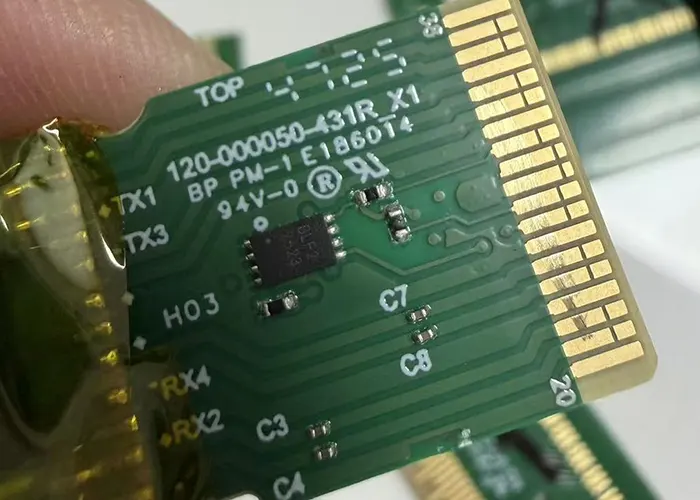
PCB gold fingers are engineered as contact interfaces to withstand repeated mating cycles. Unlike solder joints, surface tribology governs their performance rather than metallurgical bonding.
Therefore, industry standards, plating system selection, and mechanical interface design determine the expected insertion/removal life, rather than treating it as a single fixed value.
In practical engineering, cycle life requirements typically range from fewer than 10 cycles in low-cost consumer electronics to more than 50,000 cycles in aerospace and defense systems.
These ranges are not arbitrary—they are consistent with industry plating specifications such as IPC and ASTM standards, as well as long-term connector reliability testing methodologies.
Industry Standard Cycle-Life Ranges by Application Class
Across PCB and connector design practices, insertion/removal life is usually defined at the system level (connector + plating + mechanical design), rather than by gold thickness alone.
However, plating systems strongly correlate with expected performance tiers.
| Application Class | Typical Use Cases | Target Cycle Life (Industry Practice) | Common Surface Finish |
|---|---|---|---|
| Low-end Consumer | Home appliances, disposable modules | < 10 cycles | ENIG or thin gold |
| Standard Electronics | Memory modules, PCIe cards, GPUs | 500 – 1,000 cycles | Hard gold (15–30 μin) |
| Industrial Systems | Controllers, instrumentation, servers | 1,000 – 10,000 cycles | Hard gold (30–50 μin) |
| High-Reliability / Military | Avionics, defense backplanes | 10,000 – 50,000+ cycles | Thick hard gold + optimized contact design |
These ranges align closely with connector qualification approaches used in IEC 60512 (electromechanical connector testing) and industry qualification practices such as JEDEC board-level reliability tests, where mating cycles are a standard stress parameter for evaluating contact degradation.
How Industry Standards Define “Cycle Life”
It is important to note that there is no single universal “PCB gold finger cycle standard.” Qualification testing frameworks define cycle life instead, including:
IEC 60512-9-1 / 60512-9-2: Mechanical durability of connectors under repeated mating
IPC-6012 / IPC-6018: Performance requirements for rigid PCBs including edge connector features
IPC-4556 / IPC-4552: Requirements for gold and nickel-gold surface finishes
ASTM B488: Gold coating thickness and hardness classification
Under these frameworks, defined factors determine cycle life, including:
Contact resistance stability (ΔmΩ threshold)
Visual wear-through of gold layer
Exposure of nickel substrate
Mechanical deformation of contact interface
A common acceptance criterion in engineering qualification is:
Contact resistance increase must remain within a defined threshold (often < 10–20 mΩ) over the required number of mating cycles.
Plating Systems and Their Relationship to Cycle Life
The plating system, rather than gold alone, fundamentally determines gold finger durability. Industry commonly uses four major surface finishes.
| Plating Type | Structure | Hardness (Knoop) | Mechanical Behavior | Cycle Suitability |
|---|---|---|---|---|
| ENIG | Ni + 0.05–0.1 μm Au | ~90 HK | Brittle wear-through | < 10 cycles |
| Soft Gold | Pure Au | ~60–90 HK | Ductile, low wear resistance | Low-cycle or RF |
| Hard Gold | Au alloyed with Co/Ni | 130–150 HK | High abrasion resistance | 500–50,000 cycles |
| ENEPIG | Ni + Pd + Au | ~110–130 HK | Balanced corrosion + wear | Mid to high reliability |
Hard gold is the dominant solution for edge connectors because alloying gold with cobalt or nickel significantly increases hardness and reduces plastic deformation during repeated sliding contact.
Gold Thickness as a Life-Cycle Multiplier
Gold thickness is a critical parameter, but its effect is strongly dependent on mechanical design and contact force distribution.
| Gold Thickness | Metric Equivalent | Reliability Level | Typical Application |
|---|---|---|---|
| 3 μin | ~0.08 μm | Very low | Test points, single-use |
| 15 μin | ~0.38 μm | Moderate | Industrial electronics |
| 30 μin | ~0.76 μm | High | Servers, telecom, military |
| 50 μin | ~1.27 μm | Very high | Aerospace, defense |
Industry reliability testing consistently shows that:
Thin gold layers fail primarily by rapid wear-through to nickel
Medium-thickness hard gold (~30 μin) maintains stable contact resistance over 1,000+ cycles
Manufacturers use very thick gold systems when lifetime stability and low maintenance cost take priority over material cost.
A key observation from connector qualification testing is that gold thickness does not scale linearly with cycle life. Instead, it acts as a wear buffer layer, delaying exposure of the nickel barrier layer.
Nickel Barrier Layer: The Hidden Reliability Driver
All PCB gold fingers rely on a nickel underlayer (typically 3–7 μm), which is far more critical than often assumed.
Its functions include:
Blocking copper diffusion into gold (prevents contamination and oxidation)
Providing mechanical adhesion strength for the gold layer
Acting as the true electrical substrate after gold wear-through
When the gold layer is depleted, the nickel layer becomes the active contact surface. However, nickel oxidizes quickly in air, leading to a rapid increase in contact resistance.
Many systems define failure at nickel exposure rather than at complete gold loss.
Mechanical Design Factors That Determine Real Cycle Life
Even with identical plating specifications, cycle life can vary significantly due to mechanical interface design.
One of the most influential parameters is contact geometry, especially chamfer angle. Industry practice typically uses a 20°–30° chamfer, with 30° being common in high-reliability designs.
This geometry controls insertion force distribution and sliding friction length.
Other mechanical parameters include:
Surface roughness (typically controlled to Ra ≤ 0.8 μm) to minimize abrasive wear
Insertion force per pin (commonly 50–150 gf) to balance contact stability and wear rate
Total connector force (often 30–50 N per assembly) depending on pin count
Dimensional tolerance (around ±0.05 mm) to avoid excessive local pressure or micro-motion wear
These parameters directly influence whether wear occurs gradually (controlled polishing) or catastrophically (localized plating breakthrough).
Environmental and Operational Stress Factors
Real-world cycle life is also heavily influenced by environmental exposure:
Temperature/Humidity (e.g., 85°C / 85% RH) accelerates nickel oxidation after wear-through
Salt fog / corrosive gases rapidly degrade exposed nickel surfaces
Vibration and micro-motion introduce fretting corrosion, one of the most damaging wear mechanisms in connectors
Thermal cycling induces expansion mismatch stress between gold, nickel, and copper layers
In high-reliability systems, environmental factors often reduce theoretical cycle life by 30–70% if not properly mitigated through design and material selection.
Engineering Summary
PCB gold finger durability is not determined by a single parameter, but by a combined system effect:
Cycle Life = f (plating hardness × gold thickness × nickel integrity × mechanical design × environment)
Among these, the most critical contributors in practice are:
Hard gold alloy composition (wear resistance baseline)
Gold thickness (wear-through time)
Mechanical contact design (wear distribution control)
Environmental protection (oxidation and fretting suppression)
Conclusion
While industry guidelines provide general cycle life ranges, actual performance is defined by a tightly coupled system of materials engineering and mechanical design.
ENIG is suitable only for low-cycle or static applications, whereas hard gold systems remain the standard for all applications requiring repeated insertion and removal.
For designers, the key takeaway is that cycle life is not a plating spec alone—it is a full connector system design parameter validated through standardized durability testing (IEC/IPC/JEDEC frameworks).
References (Standards & Technical Sources)
IEC 60512 Series — Connectors for electronic equipment testing methods
IPC-4552 — Specification for Electroless Nickel/Immersion Gold (ENIG)
IPC-4556 — Specification for Electrodeposited Gold Plating
IPC-6012 — Qualification and performance specification for rigid PCBs
ASTM B488 — Standard specification for electrodeposited gold coatings
JEDEC JESD22-B111 — Board-level reliability test methods
Holm, R. — Electric Contacts: Theory and Application
ASM Handbook, Volume 5 — Surface Engineering