At the center of every modern electronic product lies one critical manufacturing decision: should the PCB use Through-Hole Technology (THT), Surface Mount Technology (SMT), or a combination of both?
For decades, the industry narrative has been simple: SMT replaced through-hole assembly because it is smaller, faster, and cheaper. While partially true, that explanation ignores the engineering realities behind high-reliability electronics, power systems, industrial controls, aerospace hardware, automotive modules, and repairable products.
In 2026, the decision between SMT and through-hole assembly is no longer just about manufacturing preference. It directly affects:
- Product reliability
- Thermal performance
- Signal integrity
- Mechanical durability
- Production scalability
- Repairability
- Long-term maintenance cost
Choosing the wrong assembly method can lead to vibration failures, overheating, difficult repairs, increased production costs, or even complete product redesigns.
The reality is more nuanced than “SMT is better.”
SMT dominates modern consumer electronics because it enables miniaturization and highly automated manufacturing. However, through-hole technology still survives—and thrives—in critical applications where mechanical strength, high current handling, or long-term durability matter more than compact size.
Even more importantly, many advanced electronic products today no longer use a single assembly method. Hybrid PCB assembly, which combines SMT and THT on the same board, has quietly become the real industry standard for complex electronics.
This guide explores the real engineering differences between SMT and through-hole assembly—not just textbook definitions. We will compare:
- Manufacturing cost
- Production speed
- Mechanical reliability
- Thermal behavior
- High-frequency performance
- Design flexibility
- Repairability
- Power handling capability
By the end, you will understand not only which method is “better,” but which one is better for your specific application.
PCB Assembly Has Changed More Than Most Engineers Realize
The Evolution From Hand-Soldered Boards to Fully Automated SMT Lines
PCB assembly began in an era dominated entirely by manual labor. Early electronic products relied on through-hole components with long leads inserted into drilled holes and soldered by hand.
During the 1960s and 1970s, dual-in-line packages (DIPs) became the industry standard. Wave soldering later improved manufacturing efficiency, enabling the automatic soldering of large batches of boards.
However, consumer electronics rapidly pushed the limits of through-hole technology.
As products became smaller, engineers encountered several major limitations:
- Large component footprints
- Low component density
- Routing restrictions caused by drilled holes
- Higher material consumption
- Increasing labor costs
The transition toward portable electronics in the 1980s accelerated the rise of SMT.
Surface Mount Technology fundamentally changed PCB manufacturing because components no longer required leads passing through the board. Instead, components were soldered directly onto surface pads.
This enabled:
| Capability | Through-Hole Era | SMT Era |
|---|---|---|
| Component density | Low | Extremely high |
| Assembly automation | Limited | Highly automated |
| PCB size reduction | Difficult | Major advantage |
| Double-sided assembly | Rare | Standard |
| Manufacturing speed | Moderate | Very high |
The smartphone revolution later pushed SMT even further. Modern package sizes such as 0201 and 01005 are now smaller than grains of sand.
Miniaturization did not merely improve aesthetics—it completely reshaped the economics of electronics manufacturing.
Why Through-Hole Never Disappeared
Despite SMT dominance, through-hole assembly never became obsolete.
The reason is simple: some engineering problems still favor physical strength over miniaturization.
Through-hole components create mechanically reinforced solder joints because their leads pass entirely through the PCB. This gives them significant advantages in environments involving:
- Constant vibration
- Mechanical shock
- High current loads
- Thermal cycling
- Connector stress
Industries that still heavily rely on THT include:
| Industry | Why THT Is Still Used |
|---|---|
| Aerospace | Extreme vibration and reliability |
| Industrial automation | Long-term durability |
| Power electronics | High-current handling |
| Military systems | Mechanical robustness |
| Automotive power modules | Thermal and mechanical stress |
Large transformers, relays, electrolytic capacitors, heavy connectors, and power semiconductors are still commonly produced in through-hole packages because SMT alternatives may not provide sufficient structural integrity.
Modern Electronics Rarely Use Only One Technology
One of the biggest misconceptions in PCB design is assuming products must choose either SMT or THT exclusively.
In reality, many advanced electronics use hybrid assembly.
A modern industrial PCB may contain:
- SMT ICs for processing and communication
- Through-hole connectors for durability
- SMT passives for density optimization
- Through-hole transformers for power handling
This mixed approach allows engineers to optimize performance, reliability, and manufacturing efficiency simultaneously.
Today, hybrid assembly is often the practical engineering solution rather than a compromise.
What Is Through-Hole Technology (THT)?
How Through-Hole Assembly Actually Works
Through-hole assembly involves inserting component leads into pre-drilled holes in the PCB.
The process typically includes:
- PCB drilling
- Component insertion
- Flux application
- Wave soldering or hand soldering
- Inspection and testing
Unlike SMT, the solder joints physically anchor components through the entire board thickness.
Two common soldering methods are used:
| Method | Typical Usage |
|---|---|
| Wave soldering | High-volume production |
| Manual soldering | Prototypes and specialized boards |
Because drilling is required, through-hole assembly increases PCB manufacturing complexity and reduces available routing space.
Types of Through-Hole Components
Through-hole components are generally divided into two categories.
Axial Components
Axial parts have leads extending from both ends of the component body.
Typical examples include:
- Resistors
- Diodes
- Small capacitors
Radial Components
Radial components have leads exiting from one side.
Examples include:
- Electrolytic capacitors
- LEDs
- Relays
Large power components also commonly use through-hole packaging because they require stronger mechanical attachment and improved thermal handling.
Why Engineers Still Trust Through-Hole
The primary advantage of through-hole assembly is mechanical reliability.
Because leads pass through the PCB, the solder joints withstand:
- Pulling forces
- Vibration
- Mechanical shock
- Connector insertion stress
Repairability is another major benefit.
Through-hole components are easier to:
- Replace manually
- Inspect visually
- Prototype with
- Modify during development
This is especially valuable in aerospace, industrial maintenance, and low-volume engineering projects.
What Is Surface Mount Technology (SMT)?
How SMT Assembly Works
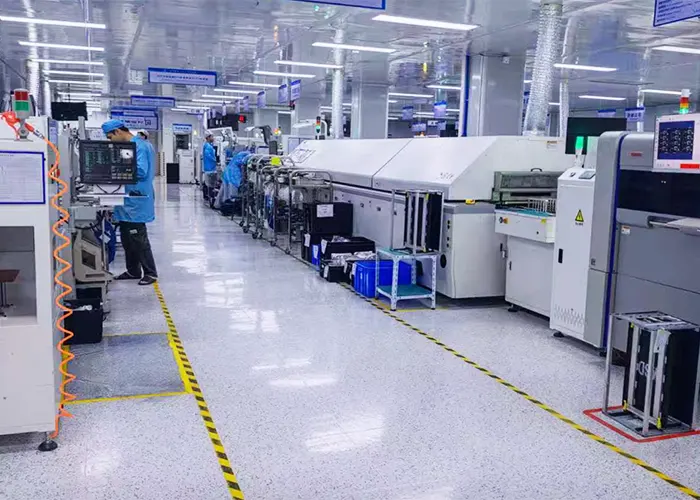
SMT assembly is a highly automated manufacturing process.
The typical workflow includes:
| SMT Process Step | Purpose |
|---|---|
| Solder paste printing | Apply solder paste to pads |
| Pick-and-place assembly | Position components |
| Reflow soldering | Melt solder paste |
| AOI inspection | Detect defects automatically |
Unlike THT, SMT does not require component leads to pass through the board.
Instead, components are mounted directly onto copper pads.
Modern SMT production lines can place tens of thousands of components per hour with extremely high accuracy.
Why SMT Became the Global Standard
SMT became dominant because it dramatically reduced manufacturing costs at scale.
The major advantages include:
| SMT Advantage | Engineering Impact |
|---|---|
| Smaller components | Compact products |
| Automated assembly | Lower labor cost |
| Double-sided placement | Higher density |
| Faster production | Mass manufacturing efficiency |
| Shorter signal paths | Better high-speed performance |
These advantages made SMT essential for:
- Smartphones
- Tablets
- Laptops
- Wearables
- IoT devices
- Networking equipment
Without SMT, modern compact electronics would not exist.
Modern SMT Components Are Shockingly Small
The scale of modern SMT packages is difficult to appreciate without magnification.
Common package sizes include:
| Package | Approximate Size |
|---|---|
| 0603 | 1.6 × 0.8 mm |
| 0402 | 1.0 × 0.5 mm |
| 0201 | 0.6 × 0.3 mm |
| 01005 | 0.4 × 0.2 mm |
Some advanced semiconductor packages now contain thousands of solder balls underneath a single chip package.
This level of miniaturization enables today’s ultra-compact consumer electronics.
SMT vs Through-Hole: The Real Differences That Matter
Board Size and Component Density
SMT clearly dominates compact electronic design.
Because components mount directly onto the board surface:
- Routing becomes easier
- Components can be placed on both sides
- PCB size shrinks significantly
Through-hole assembly consumes more board area because drilled holes reduce routing channels.
In multilayer high-density PCBs, excessive through-holes can severely complicate layout optimization.
Manufacturing Speed
SMT production is vastly faster than through-hole assembly.
Modern pick-and-place systems can exceed:
| Assembly Method | Typical Placement Speed |
|---|---|
| Manual THT | Hundreds/hour |
| Automated THT | Few thousand/hour |
| Modern SMT line | 30,000–100,000+/hour |
This automation advantage is one of the main reasons SMT dominates consumer electronics manufacturing.
Reliability Under Mechanical Stress
This is where through-hole still maintains a strong advantage.
In high-vibration environments, through-hole leads mechanically reinforce the solder joints.
Applications benefiting from THT include:
- Aircraft electronics
- Railway systems
- Industrial motor controls
- Heavy machinery
SMT solder joints are smaller and more vulnerable to:
- Fatigue cracking
- Mechanical stress
- Repeated thermal cycling
However, modern SMT reliability has improved substantially with better solder alloys, underfill materials, and PCB design techniques.
Signal Integrity and High-Speed Electronics
For high-frequency circuits, SMT usually performs better.
Shorter lead lengths reduce:
- Parasitic inductance
- Signal reflections
- Electromagnetic interference
This makes SMT ideal for:
- RF circuits
- High-speed digital systems
- 5G hardware
- Advanced computing systems
Through-hole leads introduce additional inductance that can negatively affect high-speed performance.
Thermal Performance
Thermal performance depends heavily on the application.
Through-hole components often dissipate heat better in high-power systems because:
- Leads provide additional thermal conduction paths
- Larger packages tolerate higher temperatures
- Mechanical mounting improves heat transfer
However, modern SMT power packages now include:
- Thermal pads
- Heat slugs
- Copper coin structures
- Bottom-side thermal vias
As a result, SMT is increasingly capable of handling high-power applications once dominated exclusively by THT.
Cost Comparison: SMT vs Through-Hole Is More Complicated Than Most Articles Claim
One of the biggest misconceptions in PCB manufacturing is that SMT is always cheaper and through-hole assembly is always expensive.
The truth is far more complex.
The real manufacturing cost depends on several interconnected factors:
- Production volume
- Board complexity
- Labor availability
- Component selection
- Repair requirements
- Automation level
- Product lifecycle expectations
A prototype aerospace controller and a million-unit smartphone motherboard operate under completely different economic models. Comparing SMT and through-hole assembly without considering production context often leads to misleading conclusions.
Why SMT Looks Expensive at First
At the equipment level, SMT manufacturing is undeniably capital-intensive.
A modern automated SMT production line may include:
| SMT Equipment | Typical Function |
|---|---|
| Solder paste printer | Precise paste deposition |
| Pick-and-place machine | Automated component placement |
| Reflow oven | Controlled solder melting |
| AOI system | Optical defect inspection |
| SPI system | Solder paste inspection |
High-speed pick-and-place systems alone can cost hundreds of thousands of dollars, while advanced production lines in large electronics factories may exceed several million dollars in total investment.
The reflow process itself also requires tight thermal control. Modern lead-free solder alloys typically operate at peak temperatures around 240–250°C, demanding sophisticated thermal profiling and process monitoring.
For small manufacturers or low-volume projects, this upfront investment makes SMT appear expensive.
However, this only tells part of the story.
Why SMT Becomes Cheaper at Scale
Once production volume increases, SMT economics change dramatically.
Automation reduces labor requirements far more effectively than through-hole assembly. Modern SMT lines can place tens of thousands of components per hour with minimal human intervention.
This creates several cascading cost advantages.
Labor Reduction
Labor is one of the largest hidden costs in PCB assembly.
Through-hole assembly still requires substantial manual operations:
- Component insertion
- Selective soldering
- Hand solder touch-up
- Connector alignment
- Inspection and rework
SMT minimizes these manual processes through automation.
In high-volume consumer electronics manufacturing, labor savings alone can reduce assembly cost significantly over large production runs.
Faster Cycle Times
SMT production throughput is dramatically higher than THT.
| Manufacturing Method | Approximate Throughput |
|---|---|
| Manual THT assembly | Hundreds of components/hour |
| Automated THT insertion | Thousands/hour |
| Modern SMT production line | 30,000–100,000+ placements/hour |
This throughput advantage directly affects:
- Factory utilization
- Production lead time
- Time-to-market
- Inventory turnover
In highly competitive industries like smartphones or networking hardware, faster production speed translates directly into financial advantage.
Smaller PCBs Reduce Total Product Cost
SMT components occupy significantly less board area than through-hole components.
This creates secondary economic benefits beyond assembly itself.
Smaller boards mean:
- Lower laminate material consumption
- Reduced copper usage
- Lower enclosure size requirements
- Reduced product weight
- Lower shipping costs
For portable electronics manufactured in millions of units annually, even a few millimeters of PCB reduction can save enormous amounts of money across the supply chain.
Hidden Costs of Through-Hole Assembly
Many PCB cost comparisons underestimate the true manufacturing burden of through-hole technology.
The most obvious issue is drilling.
Every plated through-hole requires:
- Precision drilling
- Hole cleaning
- Copper plating
- Additional inspection
As PCB layer counts increase, drilling complexity and cost rise significantly.
Manual Insertion Still Slows Production
Although automated through-hole insertion equipment exists, many THT operations still involve manual labor.
This creates several inefficiencies:
| Through-Hole Challenge | Manufacturing Impact |
|---|---|
| Manual insertion | Slower throughput |
| Human variability | Increased defect risk |
| Wave solder masking | Extra processing |
| Connector alignment | Additional labor |
Through-hole inspection is also slower because solder joints may need visual verification from both sides of the PCB.
Larger PCB Area Increases Material Cost
Through-hole routing consumes valuable PCB real estate.
Because leads pass through the board:
- Routing channels become restricted
- Layer transitions become more complicated
- PCB size often increases
This becomes especially problematic in multilayer high-density designs where routing congestion directly impacts manufacturing yield.
The Surprising Area Where Through-Hole Can Actually Save Money
Despite these disadvantages, through-hole assembly still offers important economic advantages in specific scenarios.
This is particularly true in low-volume manufacturing and prototyping.
For small engineering runs, the setup cost of SMT can outweigh its automation benefits.
A manually assembled through-hole prototype may actually be cheaper because it avoids:
- SMT stencil fabrication
- Pick-and-place programming
- Reflow profiling
- AOI setup time
Easier Repair Reduces Long-Term Ownership Cost
Field servicing is another overlooked factor.
Through-hole components are generally easier to:
- Replace
- Diagnose
- Rework
- Modify in the field
This matters enormously in industries where products remain operational for decades.
Examples include:
- Industrial automation systems
- Power infrastructure equipment
- Aerospace electronics
- Laboratory instruments
In these environments, repairability may matter more than manufacturing speed.
A board that costs slightly more initially but can be repaired repeatedly may have a lower total lifecycle cost.
Through-Hole vs SMT Reliability: Which Lasts Longer?
Reliability discussions around SMT and through-hole technology are often oversimplified.
Many articles claim through-hole is always more reliable. Others argue modern SMT has completely surpassed THT.
Both claims ignore application context.
Reliability depends on the specific stress environment:
- Mechanical vibration
- Thermal cycling
- Electrical load
- Humidity exposure
- Shock events
- Long-term fatigue behavior
Different assembly methods respond differently to each condition.
Why Through-Hole Dominates in Aerospace and Military Electronics
Through-hole technology remains heavily used in aerospace, defense, and mission-critical industrial electronics for one primary reason:
Mechanical robustness.
Because component leads physically pass through the PCB, solder joints are mechanically reinforced by the board itself.
This creates stronger resistance against:
- Vibration
- Mechanical shock
- Connector stress
- Thermal expansion mismatch
In aerospace systems, electronics may experience:
| Environmental Stress | Typical Severity |
|---|---|
| Continuous vibration | Extreme |
| Thermal cycling | Severe |
| Mechanical shock | Frequent |
| Long operational lifespan | 15–30+ years |
Under these conditions, through-hole connections often provide superior long-term durability.
Large connectors, transformers, relays, and power devices especially benefit from through-hole reinforcement.
SMT Reliability Is Better Than Many People Think
Modern SMT reliability has improved dramatically over the past two decades.
Early SMT assemblies were more vulnerable to cracking and solder fatigue due to:
- Smaller solder joints
- Inferior solder alloys
- Less advanced reflow control
Today, however, SMT manufacturing includes major reliability improvements:
| SMT Reliability Improvement | Engineering Benefit |
|---|---|
| Lead-free alloy optimization | Improved fatigue resistance |
| Nitrogen reflow systems | Reduced oxidation |
| Underfill materials | Better shock resistance |
| AOI and X-ray inspection | Higher defect detection |
| Thermal profiling software | More consistent solder joints |
Modern automotive ECUs, telecom infrastructure, and medical electronics rely heavily on SMT and routinely achieve extremely high reliability standards.
In many cases, SMT reliability failures today are more related to poor design practices than to SMT itself.
The Biggest SMT Reliability Risks
Although SMT reliability has improved significantly, several failure mechanisms remain important.
Pad Cratering
Pad cratering occurs when mechanical stress fractures the PCB laminate beneath SMT pads.
This failure mode is especially common in:
- Drop-tested consumer electronics
- Thin mobile devices
- Large BGAs on flexible boards
Solder Fatigue
Repeated thermal cycling causes solder joints to expand and contract.
Over time, microscopic cracks can develop.
This issue becomes more severe when:
- Temperature swings are large
- Components are mechanically heavy
- Coefficient-of-expansion mismatch exists
Head-in-Pillow Defects
Head-in-pillow defects occur when solder balls fail to fully merge during reflow.
The result is intermittent electrical contact that may pass initial testing but fail later in the field.
Advanced X-ray inspection is often required to detect these hidden failures.
Which Technology Handles Vibration Better?
In pure mechanical vibration resistance, through-hole generally maintains an advantage.
Industrial machinery, railway electronics, and military systems often continue using THT for connectors and large components because lead anchoring physically reinforces the assembly.
However, modern SMT reliability under vibration is far better than many engineers assume.
Automotive electronics provide a strong example.
Modern vehicles contain dozens of SMT-based electronic control units exposed to:
- Engine vibration
- Road shock
- Wide temperature swings
- Moisture exposure
Yet these systems routinely achieve operational lifetimes exceeding 10–15 years.
The difference is that automotive SMT designs use advanced engineering strategies such as:
- Underfill reinforcement
- Corner bonding adhesives
- Controlled PCB flexure
- Thermal stress optimization
The real conclusion is not that one technology is universally more reliable.
Instead:
- Through-hole is inherently stronger mechanically
- SMT can achieve excellent reliability with proper engineering design
Repairability and Maintenance: The Forgotten Engineering Factor
Most SMT vs through-hole comparisons focus only on manufacturing cost and component density.
Very few discuss repairability.
This is increasingly important as industries face growing pressure around:
- Electronic waste reduction
- Product lifespan extension
- Sustainability regulations
- Right-to-repair legislation
Repairability is no longer just an engineering issue—it is becoming a regulatory and environmental issue.
Why Technicians Love Through-Hole Boards
Through-hole electronics remain much easier to service manually.
Technicians benefit from:
| Through-Hole Advantage | Maintenance Benefit |
|---|---|
| Larger components | Easier handling |
| Visible solder joints | Faster inspection |
| Strong pads | Lower rework damage risk |
| Standard tools | Simpler repair workflow |
A damaged resistor or capacitor can often be replaced using basic soldering equipment without requiring expensive rework systems.
This simplicity matters in field servicing environments where advanced repair infrastructure may not exist.
Why SMT Repair Is Difficult
Modern SMT packages have become extremely small.
Repairing fine-pitch SMT components often requires:
- Hot air rework stations
- Infrared heaters
- Microscopes
- Precision solder paste application
- X-ray verification for BGAs
The risk of PCB damage also increases substantially during SMT repair.
Pads can delaminate or lift from excessive heat, especially on multilayer high-density boards.
For ultra-miniaturized electronics, repair may become economically impractical.
In many consumer products, replacement is now cheaper than repair.
Right-to-Repair and Electronics Sustainability
This issue has become increasingly controversial.
Globally, electronic waste generation continues to rise rapidly, while many modern electronic products remain difficult or impossible to repair economically.
Several governments are now introducing stronger right-to-repair regulations aimed at:
- Extending product lifespan
- Improving repair accessibility
- Reducing e-waste
- Encouraging modular electronics design
In this context, through-hole technology unexpectedly regains relevance.
While THT may appear outdated from a miniaturization perspective, it often supports:
- Longer product service life
- Easier refurbishment
- Lower maintenance cost
- Reduced electronic waste generation
This creates an interesting industry paradox:
The most technologically advanced assembly method is not always the most sustainable one.
When SMT Is Clearly the Better Choice
Despite the strengths of through-hole assembly, there are many applications where SMT is unquestionably superior.
Smartphones and Wearables
Modern smartphones would be physically impossible using traditional through-hole assembly.
Extreme miniaturization demands:
- Ultra-small packages
- Double-sided placement
- High-density routing
- High-speed signal optimization
SMT enables all of these simultaneously.
IoT Devices
Internet of Things products depend heavily on compact low-power electronics.
SMT supports:
- Small wireless modules
- Battery-powered operation
- Lightweight enclosures
- Automated mass production
For large-scale IoT deployment, SMT is effectively mandatory.
Consumer Electronics
Cost-sensitive mass-market products overwhelmingly favor SMT because automation dramatically lowers unit cost at scale.
Examples include:
- TVs
- Tablets
- Smart home devices
- Gaming systems
- Networking hardware
High-Speed Communication Hardware
RF and high-frequency digital systems benefit from SMT’s shorter electrical paths.
Lower parasitic inductance improves:
- Signal integrity
- EMI performance
- High-speed timing stability
This makes SMT essential for:
- 5G hardware
- Data centers
- High-speed networking equipment
Medical Miniaturized Electronics
Portable medical electronics increasingly rely on SMT because smaller products improve portability and patient comfort.
Examples include:
- Wearable monitoring devices
- Implantable electronics
- Portable diagnostic equipment
Miniaturization is often a functional requirement rather than simply a market preference.
Key Takeaway
SMT is usually the better choice when:
- Product size matters
- Manufacturing volume is high
- Automation is critical
- High-speed performance is required
- Weight reduction matters
- Production scalability is essential
Through-hole still plays an important role—but SMT has become the foundation of modern electronics manufacturing because it aligns with the industry’s long-term direction toward smaller, faster, lighter, and more automated products.
When Through-Hole Still Wins
Despite SMT’s dominance in modern electronics, through-hole technology (THT) remains indispensable in several engineering domains. Its continued use is not a legacy constraint but a deliberate design choice driven by mechanical, electrical, and environmental requirements that SMT cannot always satisfy.
The fundamental advantage of through-hole construction is mechanical anchoring. Because component leads pass through the PCB and are soldered on the opposite side, the joint behaves like a riveted structure rather than a surface bond. This becomes critical when boards are exposed to shock, vibration, or sustained mechanical load.
Power Supplies and Industrial Controllers
Power electronics represent one of the strongest remaining domains for through-hole adoption.
High-current components such as transformers, large inductors, and electrolytic capacitors generate both thermal and mechanical stress during operation. Through-hole mounting improves heat spreading through copper vias and mechanical stability under load.
In industrial motor drives and switching power supplies, design margins are often conservative. Many manufacturers still specify through-hole for components exceeding:
- 5–10 A continuous current paths
- High-voltage isolation components
- Bulk energy storage capacitors
This is less about manufacturing tradition and more about predictable failure behavior under long-term stress.
Aerospace and Defense Electronics
Aerospace systems require extremely long operational lifetimes, often exceeding 15–30 years, with minimal maintenance opportunities.
Through-hole technology is widely used in:
- Avionics power distribution units
- Flight control systems (legacy and hybrid architectures)
- Missile guidance electronics
- Space-qualified instrumentation modules
The reason is simple: mechanical reliability under vibration and thermal cycling.
Unlike consumer electronics, aerospace systems are validated under qualification standards such as MIL-STD-810 (environmental stress testing) and MIL-STD-202 (component reliability), where vibration endurance is a critical parameter.
Automotive Electronics
Modern automotive systems increasingly use SMT, but through-hole remains essential in specific subsystems.
Typical applications include:
- Relay modules
- High-current connectors
- Ignition and power distribution components
- Engine bay electronics exposed to thermal extremes
Automotive environments combine three stress factors simultaneously:
- Continuous vibration
- Wide temperature cycling (-40°C to 125°C typical qualification range)
- Moisture and contamination exposure
Through-hole mounting provides additional mechanical anchoring that reduces solder joint fatigue under these combined stresses.
Connectors and Transformers
Connectors are one of the most persistent use cases for through-hole technology.
The insertion and extraction forces applied to connectors can exceed the shear strength of SMT pads, especially in industrial or automotive environments.
Similarly, transformers and large inductive components generate both:
- Mechanical stress due to mass
- Thermal expansion during operation
Through-hole mounting distributes these stresses through the PCB structure rather than concentrating them on surface pads.
Prototype and Educational Boards
In prototyping environments, flexibility often outweighs optimization.
Through-hole components allow:
- Rapid manual assembly
- Easy replacement and modification
- Breadboard compatibility
- Low-cost iteration
This is why platforms such as Arduino-style development boards still rely heavily on through-hole connectors and headers, even when internal ICs use SMT packages.
Key Takeaway
Through-hole is the preferred choice when:
- Mechanical strength is critical
- High current or voltage is involved
- Field repairability is required
- Environmental stress is high
- Rapid prototyping or modification is needed
The Hybrid PCB Revolution: Why Modern Boards Use Both
Modern electronics rarely conform to a single assembly method. Instead, most advanced PCBs use a hybrid architecture combining SMT and through-hole technologies.
This approach is not a compromise—it is an optimization strategy.
What Hybrid PCB Assembly Really Looks Like
A typical hybrid PCB design separates functions based on physical and electrical requirements:
| Component Type | Preferred Method |
|---|---|
| Microcontrollers / ICs | SMT |
| Passive components | SMT |
| RF circuits | SMT |
| Power connectors | Through-hole |
| Transformers / inductors | Through-hole |
| Mechanical interfaces | Through-hole |
For example, a switching power supply board may use:
- SMT for control logic and signal processing
- Through-hole for power input terminals
- Through-hole for high-current energy storage components
This separation allows each technology to operate within its optimal performance envelope.
Why Hybrid Designs Are Increasing
Hybrid assembly has grown significantly due to the increasing complexity of modern electronics.
In industries such as electric vehicles and industrial automation, a single PCB must simultaneously handle:
- High-speed digital processing
- High-current power distribution
- Harsh environmental conditions
Key drivers include:
- Electric vehicles (battery management + power conversion)
- Industrial robotics (power + precision control)
- AI hardware systems (dense computation + thermal constraints)
In EV battery management systems (BMS), for example, SMT handles sensing and control logic, while through-hole is used for high-current connectors and power switching elements.
The Manufacturing Challenges of Hybrid Assembly
Although hybrid designs are powerful, they introduce manufacturing complexity.
Compared with pure SMT production, hybrid PCB assembly requires:
- Multiple soldering processes (reflow + wave or selective soldering)
- Complex thermal profiles to avoid damaging SMT components during THT soldering
- Increased inspection steps (AOI + manual verification)
- More precise process sequencing
A typical hybrid manufacturing flow might include:
- SMT assembly and reflow soldering
- Inspection (AOI / X-ray for critical joints)
- Through-hole component insertion
- Selective or wave soldering
- Final inspection and testing
This increases process control requirements and can raise manufacturing cost for low-volume production—but improves system-level reliability.
The Engineering Decision Framework (Most Important Section)
Rather than treating SMT vs through-hole as a binary choice, engineers should evaluate the decision using functional requirements.
This section converts the discussion into a practical engineering tool.
Choose SMT If Your Product Needs…
SMT is optimal when design priorities include:
- Miniaturization and compact form factor
- High-volume automated manufacturing
- High-speed signal integrity (RF / digital systems)
- Low per-unit production cost at scale
- Lightweight design constraints
SMT becomes the default choice in modern consumer and communication electronics because it maximizes density and manufacturing efficiency.
Choose Through-Hole If Your Product Needs…
Through-hole is more appropriate when:
- Mechanical robustness is critical
- High current or high voltage handling is required
- Field repair and maintenance are expected
- Environmental stress is severe (shock, vibration, thermal cycling)
In these cases, mechanical reliability outweighs spatial efficiency.
Choose Hybrid Assembly If Your Product Needs…
Hybrid architecture is the correct approach when systems must balance conflicting requirements:
- High-power + high-density logic on the same board
- Mixed environmental stress conditions
- Long lifecycle industrial deployment
- Multi-domain functionality (control + power + communication)
Hybrid design is now the dominant strategy in advanced electronics such as EV systems, industrial automation, and aerospace subsystems.
Common Mistakes Engineers Make When Choosing SMT or THT
Many PCB design failures are not due to technology limitations, but incorrect assumptions during early design stages.
Designing THT for Consumer Electronics
Using through-hole in compact consumer devices often leads to unnecessary:
- PCB size increases
- Higher material cost
- Reduced automation efficiency
This is one of the most common legacy design inefficiencies.
Using SMT Connectors in High-Vibration Systems
SMT connectors may fail prematurely under repeated mechanical stress if not properly reinforced.
Without mechanical anchoring or support structures, solder joints may experience fatigue cracking over time.
Ignoring Thermal Expansion Stress
Different materials expand at different rates.
Failure to account for coefficient of thermal expansion (CTE) mismatch can lead to:
- Solder joint fatigue
- Pad delamination
- Micro-cracking in multilayer boards
This is particularly important in automotive and power electronics.
Underestimating Rework Costs
SMT repair is significantly more expensive due to:
- Specialized equipment requirements
- Risk of pad damage
- Microscale component handling
Designs that require frequent modification may become economically inefficient if SMT is overused.
Choosing Based Only on Initial Cost
Focusing solely on manufacturing cost ignores lifecycle considerations such as:
- Maintenance cost
- Failure rates
- Repairability
- Downtime cost
In industrial systems, lifecycle cost often exceeds production cost by several multiples.
Future Trends in PCB Assembly
PCB assembly technology continues to evolve, driven by miniaturization, automation, and sustainability demands.
Ultra-Miniature SMT Components
Package sizes continue to shrink beyond 0201 and 01005 formats, enabling:
- Higher functional density
- Smaller wearable systems
- Increased AI hardware integration
Robotic Through-Hole Automation
Through-hole assembly is becoming increasingly automated through:
- Robotic insertion systems
- Selective soldering robots
- Vision-guided component alignment
This reduces the traditional labor disadvantage of THT.
AI-Based Optical Inspection
Artificial intelligence is now used in AOI systems to:
- Detect micro-defects
- Improve false-positive reduction
- Adapt inspection parameters dynamically
This significantly improves quality control efficiency in high-volume SMT production.
Advanced Lead-Free Soldering
Lead-free solder alloys continue to evolve to improve:
- Thermal fatigue resistance
- Wetting performance
- Long-term mechanical stability
These improvements directly enhance SMT reliability.
Sustainable PCB Manufacturing
Environmental regulations are pushing the industry toward:
- Reduced electronic waste
- Repairable design standards
- Recyclable materials
- Longer product lifecycles
This trend may indirectly increase the relevance of through-hole and modular hybrid designs in industrial systems.
Conclusion: SMT vs Through-Hole Is Not a Competition—It Is an Engineering Allocation Problem
The comparison between SMT and through-hole technology is often framed as a replacement story, but that framing is outdated.
SMT did not eliminate through-hole assembly; it redefined where each technology provides the highest engineering return.
SMT became the backbone of modern electronics because it aligns with the dominant constraints of the industry:
miniaturization, automation, high-speed signal integrity, and cost efficiency at scale. It enables the dense, lightweight, high-performance systems found in smartphones, computing hardware, IoT devices, and communication infrastructure.
In virtually all high-volume consumer markets, SMT is no longer optional—it is structurally necessary.
However, through-hole technology persists because it solves a different class of problems that SMT does not fully replace.
When mechanical stress, vibration, thermal cycling, high current, or long-term serviceability become primary design constraints, through-hole connections still provide superior mechanical anchoring and more predictable failure behavior.
This is why it remains deeply embedded in aerospace, industrial control systems, automotive power modules, and field-repairable equipment.
The most important shift in modern PCB engineering is not SMT replacing THT, but the normalization of hybrid assembly. Contemporary systems increasingly distribute functions across both technologies:
SMT for computation and signal density, and through-hole for mechanical interfaces and power handling.
This hybrid approach reflects a more mature engineering mindset—optimizing at the system level rather than forcing a single technology to satisfy conflicting requirements.
Ultimately, the correct answer to “which is better” depends entirely on context.
SMT is superior when performance, density, and scalability dominate design priorities. Through-hole is superior when robustness, thermal endurance, and serviceability define system value.
In advanced electronics, both are often required simultaneously.
The real engineering skill is not choosing SMT or through-hole in isolation, but allocating each method precisely where it performs best within the same product architecture.